Topographica Model Editor
The Model Editor allows you to view, manipulate or create a Topographica model. By combining pre-defined components and changing each component’s parameters, you can produce useful models without any programming. The result can then be saved to a .ty script, which you can edit to add any features not yet supported by the Model Editor.
Opening the Model Editor
The model editor can be accessed through the Topographica console. Select the Simulation menu in the console’s top menu bar, and choose the model editor. A new window will appear with a toolbar on the left, a view bar at the top and a work area in the middle.
Viewing a Model
For an existing model, the model editor allows you to see how the components of the model are connected, as well as allowing you to change the properties of any component.
First load the model you wish to visualise and then open a model editor window (as described above). The model editor will automatically display the existing model. The location of each Sheet will typically be random initially, but the Sheets can be rearranged using the Move tool.
Representations
There are two main classes of component used to define a model: Sheets and Projections.
Sheets are the main computational unit in Topographica and are represented by a parallelogram. The default view indicates the size and shape of the sheet. The editor also allows you to plot a density grid over the sheet. This grid indicates how closely packed the neurons are on a sheet. This can be achieved by right clicking in the main window and selecting Toggle Density Grid from the Sheet options menu. The other option, Toggle Activity, allows you to display the actual activity of the sheets. If you only want to view the activity of one sheet then right click on the particular sheet and select Activity from the Change View menu. The activity of each neuron of the sheet is plotted onto the parallelogram, so the density of the sheet will determine how detailed the image appears.
Although the sheets are the main units, they are each independent of one another, and thus they need some form of connection to be a functioning network. Projections form a uni-directional connection between sheets, allowing activity to propagate through a model. The projections allow each neuron on one sheet to be connected to a certain area on the other sheet; this area is called the neuron’s ConnectionField. The default view plots a ConnectionField to scale. Other views can be selected by right clicking on the desired projection, and selecting Fixed Size (to turn off the size scaling) or Line (to connect Sheets using a plain line rather than a rendition of a ConnectionField).
The editor represents connections that join a sheet to itself as a dotted ellipse around the centre of the sheet. These projections allow each neuron on a sheet to be stimulated by the previous activity within a localized area. A looped line is used as the line representation of the projection.
The name of each sheet and projection is displayed beside its representation in the canvas. To find out the name of a projection that links a sheet to itself, hover the mouse over the representation. If it is not obvious which name is linked with an item, right click on the representation and select Properties. The name is displayed at the top of the window. To view other properties of a component refer to section The Parameters, which describes the properties window.
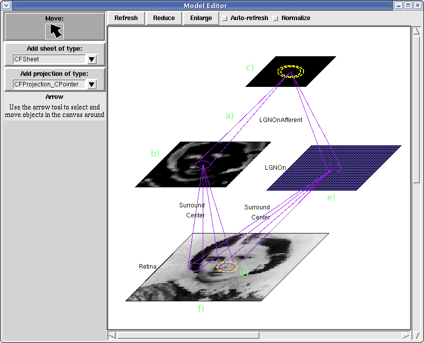
In this image you can see the representations used in the model editor for sheets and connections. a) marks a connection that joins from sheet b) to sheet c). The representation for connections to and from the same sheet is marked d) and a density grid and activity plot can be viewed on e) and f) respectively:
Creating a Model
Creating a new model for Topographica can be achieved in two ways. If you have programming experience, the most flexible option is to define a model directly using Python script, usually starting with one of the scripts that are distributed with Topographica in the examples directory. A much simpler, though more limited, approach is to use the model editor to either create a brand new model, or manipulate an existing model.
To create a new model, you need to specify the computational elements required and how they should be connected. First, open a new model editor window as described in Opening the Model Editor. If a model is loaded, the editor work area will display the model as described in Viewing a Model. Now you are ready to specify your model.
Toolbar
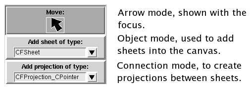
On the left hand side of the editor is a toolbar that sets the mode of the editor’s work area. There are three items; the arrow, for selecting and moving items in the window; an object pull down, allowing you to enter a new sheet into the window; a connection pull down, allowing you to make connections between sheets in the window:
The Work Area
The main part of the editor is the work area (canvas), this displays a representation of the model that Topographica is currently using. If you haven’t opened a model, this area will be empty. The first thing you may want to do is add a sheet to the model. Click on the sheet pull down menu and a list of all the types of sheet available to you will appear. This list is formed from the pre-defined library of Topographica, covered later. Select the type of sheet that you want to be part of your model. For example, you may wish to provide some stimulus to the model by using a GeneratorSheet, in this case you would select GeneratorSheet from the menu. Notice that the focus of the toolbar will have shifted to the object item. Click in the canvas, and a sheet of the type you selected will be added to the model. You can repeat this process until you have all the sheets you require for your model.
To allow responses to propagate through your model, you need to connect the sheets together. Click on the connection pull down and a list of all the existing types of projections will be presented. This list collects the pre-defined projections available to Topographica and is described later. Select the type of projection you want, for example, for a standard connection with a receptive field select a CFProjection. The canvas is now in connection mode, this means it will expect you to drag the mouse from one sheet to another (or to the same sheet for feedback connections). To do this click and hold the mouse over the sheet you want the connection to be from. Then, while holding the mouse button down, move the mouse to the sheet you want to be connected to. Release the mouse button:
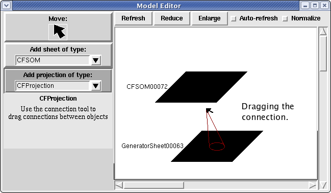
If the target location is near to an existing sheet, this will form a connection between the two sheets and you will see the clear representation for the connection as shown above. If you have selected a sheet, but decide you don’t want a connection, release the mouse in an area without any other components. To connect a sheet to itself, simply select the sheet and release the mouse while it is still over the same sheet.
The Predefined Components
Topographica supplies a library of components, composed of both basic and specific sheets and projections. To understand what a particular component does you should consult the Library section of the reference manual, or look at the online help for an object in the Parameters window (below). The Library section is divided into several different parts, so you can view all the possible sheets or projections available to you and use their descriptions to understand how you can use them in your model.
The model editor’s lists populate themselves from this library, so all the components described in the manual will be available for you to use in the editor. The editor places no restrictions on how you connect these components together, but some combinations that are not supported may give error messages.
Extending the Library
The Topographica team are regularly making additions to the library and these additions are automatically available in the model editor. If you decide to extend any of the components, simply save the files in the same directory as the others of that type (or load it into Python beforehand from any file) and your extension will automatically be available for use in the model editor.
The Parameters
All of the components that you can use to define a Topographica model have parameters. Parameters are attributes that allow you to control the behaviour of your components. To view the parameters that a component has, right click on the component’s representation in the work area. This will bring up a window with the component’s name at the top and several entries underneath. You will notice that these entries vary in style, for a description of the various types of parameter and valid changes you can make to the parameters refer to Controlling simulation parameters in the User Guide. Some examples of entry methods are, sliders for real numbers or pull down menus for class selectors and enumerations. In these cases you can simply move the slider or select a different option from the menu to change the parameter’s value:
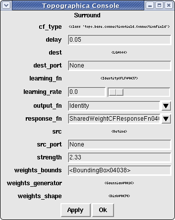
Many of the parameters will be set to a value that is an object with its own parameters. In this case, right clicking on the value will allow you to open a Properties window, which works just the same way as the main Properties window for that object but sets values on the sub-object instead.
Help for most of the options can be obtained by hovering the mouse over the option’s name. Help for the entire object can be obtained by hovering over the object’s name (‘Surround’ in this case).
Once you have made the necessary changes, clicking Apply sets these changes on the component. Clicking Close shuts the window, unless there are unapplied changes, in which case you can choose to save them before the window closes. (Clicking the window’s close icon—often an X in the top-right corner—has the same effect as clicking ‘Close’.)
In addition to the Close and Apply buttons, a Defaults button is also available for existing components (but not for new ones). This button allows you to return the displayed values to their class defaults . As with other changes, you must click Apply before they take effect.
Finally, the Refresh button updates the displayed values to those currently set on the component. Hence, it serves as a ‘reset’ button when there are unapplied changes, but also allows you to update the displayed values to the ones currently on the component if the compenent has been altered outside the GUI (at the commandline, for instance).
Changing constants and default values
The Parameters section of the User Guide also details that a parameter can be declared as a constant. This means you cannot change it once the component has been made. To ensure consistency, the model editor must create the components as soon as you make them in the editor, so these values must already be set. To set constant values (as well as default values in general) before instantiating the object, the parameters of the object about to be created can be changed using the parameters listed underneath the toolbar.
Saving a new or modified model
The Topographica console Simulation menu offers two options for saving simulations once you are done editing them: ‘Save snapshot’ and ‘Save script’.
‘Save snapshot’ saves a complete record in a .typ file of all state of the current simulation, which allows that simulation to be restored with exactly the same state later. However, because this option requires saving a large portion of the internal state of Topographica, the snapshot file might not be loadable in a different version of Topographica after an upgrade. Thus .typ snapshots should be considered only temporary storage for a model.
‘Save script’ instead generates a Python script that, when run, will generate a model with the same architecture as the one currently in memory. This option is generally more useful for models created in the Model Editor, because the resulting text file has very little of the internal state of Topographica, and it can easily be edited when necessary to work with other Topographica versions. Moreover, the resulting .ty script can be edited to add features not yet supported by the Model Editor. Thus it is generally best to save a new model as a .ty script rather than a .typ snapshot. Note that some editing of the .ty script may be necessary to make the script truly runnable, for features that have not yet been updated to provide good script representations, but such changes are typically quite minor.